The Vibration Damping Module, VDM for short, is a very handy thing to have, both for hands on learning about piezoelectric response to vibration and also for developing circuitry aimed at interfacing with piezo devices intended to be used in vibration environments.
So what is the Vibration Damping Module, and what is it used for? In this post, I'll answer those questions and give you a comprehensive overview of the VDM that includes:
- What is the Vibration Damping Module (VDM)?
- What is the Vibration Damping Module useful for?
- Equivalence of Voltage Input to Shaker Table Input
- Demonstrating Vibration Control with Piezo
- Active Control Experiments with the Vibration Damping Module
- Energy Harvesting with the Vibration Damping Module
- Conclusion and Additional Resources
What is the Vibration Damping Module (VDM)?
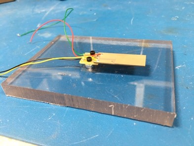
Here’s the construction I call the "Vibration Damping Module" mounted as a cantilevered beam.
Here is a top view of the vibration damping module:
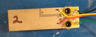
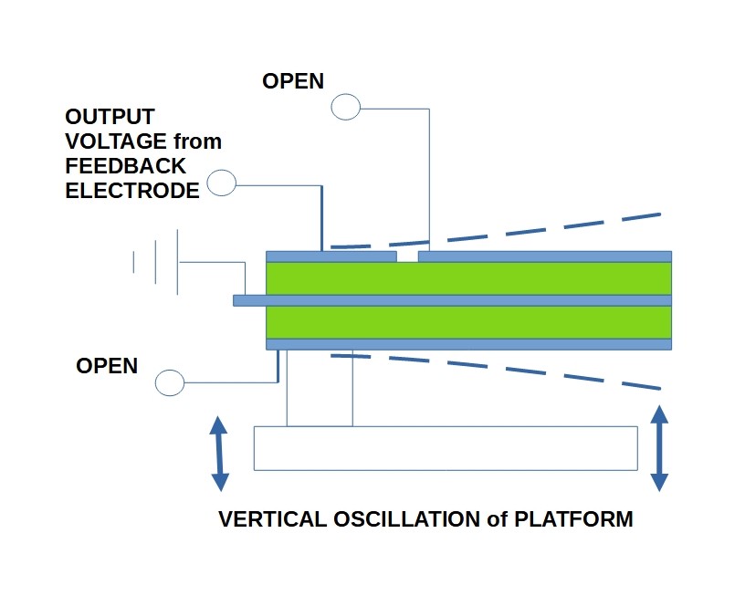
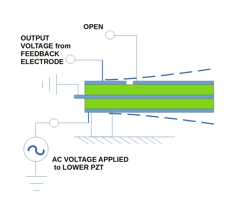
The Vibration Damping Module is a bimorph variation that has four electrical contact points:
- The center conductive layer which is kept at ground potential as a reference for all supplied or sensed electrical potentials
- A small section of isolated electrode (piezo feedback patch) near the root of the cantilever which acts as a strain gauge, producing voltage proportional to beam’s deflection.
- The lower PZT layer can be driven at an independent constant voltage, variable frequency signal to introduce vibration into the beam.
- The upper PZT layer that can be used to counteract beam vibrations either by attaching a passive energy dissipating network of components (resistors & inductors), an active energy dissipating network (i.e a harvester circuit), or by constructing some active "smart" circuit that applies a voltage with the proper timing and strength to diminish the vibration.
What is the VDM Useful for?
There are several things in the way of vibration control that this VDM construction could be used to study, however here we will focus on three:
- Demonstration of passive vibrational control via electrical component damping with piezo material. In the simplest example, this is accomplished by diverting power generated in the upper piezo layer into a single resistor.
- Demonstration of active control of vibrational response to external vibrational stimulus using piezo material. This is accomplished by using the feedback patch output voltage as an input to a PID vibration circuit.
- Demonstration of piezo energy harvesting.
Normally these studies require an external shaker table or other mechanical contrivance to initiate the vibration that is to be controlled. When AC voltage applied to the lower PZT layer however, it actually induces vibration equivalent to an external vibrational base excitation of the beam, i.e. the Vibration Damping Module is its own shaker table! So circuit development and circuit demonstrations can be accomplished right on the EE's bench without the need for a shaker table.
Equivalence of Voltage Input to Shaker Table Input
Seems like a good idea, but how do we know that the VDM actually does simulate a bimorph that is being accelerated from its base?
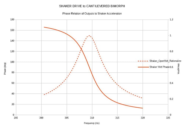
Here are two graphs of ANSYS Finite Element Model (FEM) simulations for amplitude and phase of the feedback patch voltage resulting from two cases:
- The base of the cantilever (i.e. mounting point) is vibrated up and down at +/- 1.0 G
- An AC voltage applied to the lower PZT layer at +/- 10 V
Shaker Drive to Cantilevered Bimorph
Shaker Driving Base of Cantilevered Bimorph
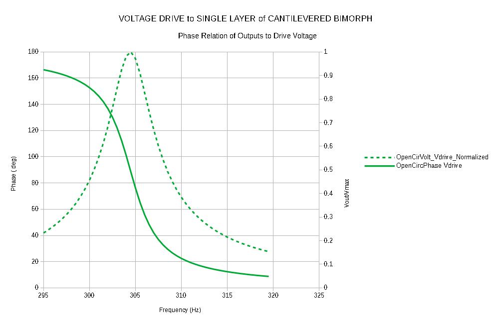
Voltage Applied to Lower PZT Area
These graphs (both with normalized amplitude) show that the open circuit voltage peak does not occur at exactly the same frequency for the base excitation case as it does for the voltage drive case, however it is quite close, and the "driving force to output voltage phase relation" is the same for base excitation as for voltage excitation. This is the key thing that makes the VDM a versatile tool for understanding and developing any kind of control circuitry from single component passives to complex PID's. You do not need a shaker table to do your circuit testing, you can do most of the work right on the electronics bench, and move on to tests under actual vibration conditions positioned well ahead of the game.
We can make the equivalence even better if we calibrate the cantilevered VDM by determining the equivalence between drive voltage magnitude and applied G’s. Then we have the ability to reproduce and test shaker table results without a shaker table!
Using the same FEM simulations that produced the above graphs we can estimate the calibration of the VDM. For the +/-10V AC drive, the feedback voltage for the resonant peak was +/-19.5V. For the +/- 1.0 G based drive the feedback voltage was +/-8.5V. So we find that an AC signal of +/- 1 Volt peak applied to the lower plate was equivalent to 0.435 G.
NOTE: This equivalence is inherently approximate. The voltage generated on the upper plate in response to stimulus (either G's or V's) represents the average stress over the volume of the upper PZT layer. Applied voltage produces a uniform bending stress in the PZT along the full cantilever length. Applied acceleration produces a non-uniform bending stress which is highest at the cantilever support, but which decreases moving along toward the end of the bimorph and actually goes to zero at the tip. The FEM analysis shows us, however, that the difference in frequency amounts to only 5 parts in 310 (1.6%), so the approximation is certainly usefully close.
Demonstrating Vibration Control with Piezo
Using a Simple Resistor to Provide Passive Damping
In this experiment we wire a single resistor from the upper piezo electrode to the center electrode (ground). The electrical power generated by the upper piezo layer (dissipated as heat in the resistor) acts as a drain on mechanical power that we put into lower piezo layer via electrical drive. If this sounds a little silly, remember that we have established an equivalence between electrically driving the lower piezo layer and vibrationally accelerating the bimorph itself, therefore the results predicted on the bench should provide a good approximation of performance on a shaker table.
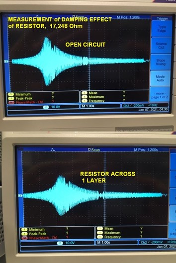
You can see from the result that the addition of that one simple resistor has a significant effect on the amplitude. At the resonant frequency (where the beam’s vibrational response to the excitation is at a maximum) the amplitude is dropped from 2.3 divisions to 1.8 divisions - about 22%. And because we calibrated the VDM, we know what that resistor would do if the flapper were put on a shaker table.
For comparison, here is the FEM estimate of the effect of the same resistor value placed across only one layer of a seismically excited bimorph.
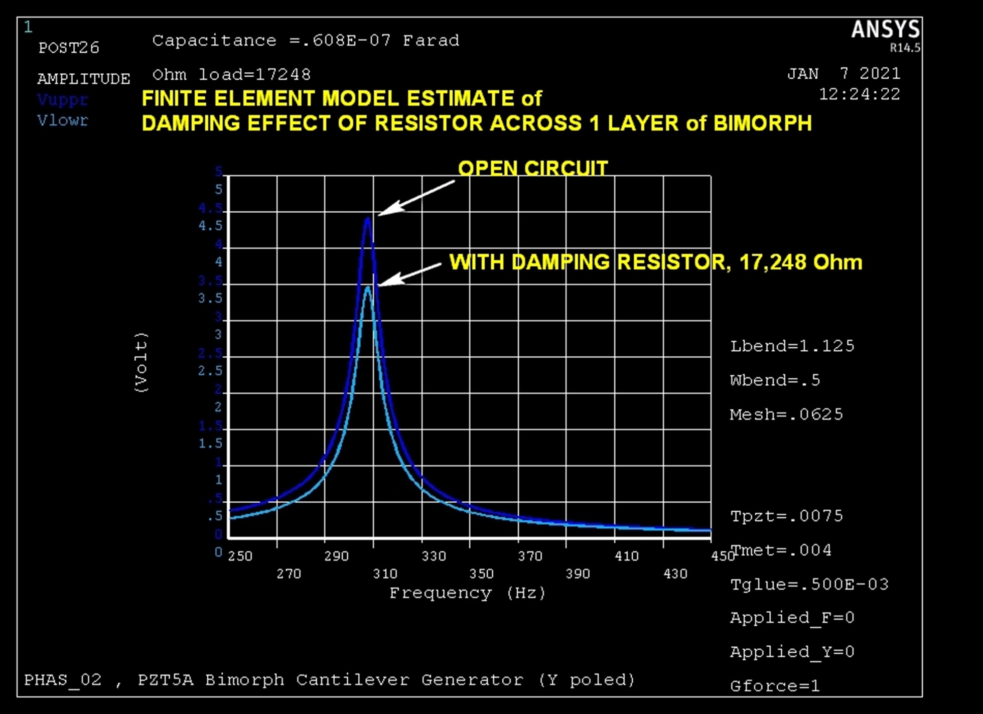
Pretty close! Determining the theoretically precise optimum value of damping resistor to use turns out not to be a simple task. Fortunately however the resistor value is not very sensitive to frequency, and you can miss the value by almost a factor of 2 without losing more than 10% of its effect. In practice the best value almost always ends up being determined empirically. For this example we used a rule of thumb which is often employed:
Set the resistor value equal to the impedance of the PZT capacitance near the frequency of interest.
R = 1/(2*pi*C*fo) = 17.268 kOhm
where
fo=337 Hz
C=27.35 nF
The Series "RL" Damper: Using an Inductor-Resistor Combination to Provide Passive Damping
This one is a little counter intuitive. In theory using the right combination of resistor and inductor can damp down the vibration level even more. Experimentally, this requires inductors with very high values typically available as iron core inductor chokes (e.g. the 20 H 154E (Hammond) from DigiKey or Mouser). This kind of component is NEVER just an inductor, it always has an associated parallel capacitance (due to the windings being packed close together in the coil) and an associated series resistance (resistance of the wire used to make the windings). There is one more tricky bit about these chokes: they exhibit additional resistance over and above the coil wire resistance that is due to eddy currents induced in the iron core. The worst part about this is that the added resistance is extremely dependent on the level of current in the coils, and it’s not a linear dependence. So it requires some careful measurements on any high value iron core inductor in the exact context of your experiments to actually be sure what your RL combination actually is, and thus to make a comparison with any predicted effect.
You’ll have to do the careful measurements, or use trial and error to find components that demonstrate the enhancements of the series RL damper over the simple R damper.
NOTE: One means of getting around the difficulties of demonstrating the RL damping effect is to utilize a "synthetic inductor," and electronic circuit which appears to the piezo as a pure high value inductor, which can be put in series with a resistor of known value. This circuit is not a passive damper. It requires power to operate, but it can help to nail down the most effective region of the inevitable L, R, and parallel C that come along with practical sized physical inductors.
For more on passive piezo damping, you can check out our on-demand webinar: Introduction to Passive Piezo Damping.
Active Control Experiments with the Vibration Damping Module
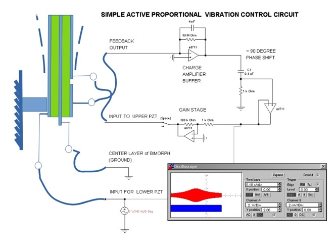
As a more "meaty" example, here is demonstration of the use of a simple proportional controller (just the "P" of "PID" ).
Key points for this control circuit example:
- We have added a unity gain “Charge Amplifier” as a buffer to the output from the PZT feedback patch. Putting this in at the beginning of the control loop greatly minimizes the parasitic effects of the connector cables between the benchtop circuit and the VDM and, leaving the feedback signal undistorted as it continues on in its journey through he circuit. This is a good measurement habit to form for piezo strain gage work in general.
NOTE: A high impedance voltage follower could also be considered, however for open frame breadboard development and AC signals the charge amplifier is more noise immune and eliminates cable length as a signal corrupter. - We shifted the feedback signal by 90 before it moves on through the circuit. Look back at the gain/phase graphs we got experimentally & with the equivalent circuit in SPICE simulation. It is out of phase approximately 90 degrees from the driving force in both cases.
- We added "Error Detection." In this case just subtracts the feedback signal from zero (i.e. ground). In other words we are telling the bimorph “STAND STILL. TRY NOT TO MOVE, NO MATTER WHAT HITS YOU!" (The input to this section could just as well be a varying voltage, indicating that we want the bimorph to be following some position vs time profile even while being by rattled by random external vibration) That might be something for you to try).
- We added the “P”, proportional gain. In this case the gain nets out between x 100 and x 300. The gain required to achieve the desired effect is something that requires a little tinkering, because it’s perfectly possible to OVER correct. Works best if you use a potentiometer and start with low gain (e.g. x 20) dialing upward slowly while watching the feedback voltage on an oscilloscope.
Here is the PID circuit (with only ‘P’ part!) that can be hooked up to the VDM:
NOTE: Regarding the opamps, the AD711’s in the circuit can be replaced by any linear opamp.
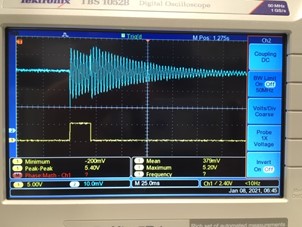
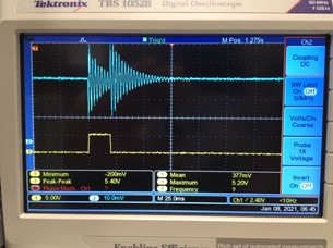
Instead of a sinewave this time, we hit the lower piezo layer with a very short pulse, only 20 milliseconds long, and see what the control circuit can do. The results are quite dramatic compared to the passive resistor damper:
Energy Harvesting with the VDM
The VDM can also be utilized to demonstrate piezo vibration energy harvesting technology, or to provide a very convenient benchtop platform for developing harvesting circuitry – from the simplest to the very sophisticated.
Here’s an example of electrical energy extraction from the VDM via a simple full wave rectifier feeding a storage capacitor and a single resistor load.
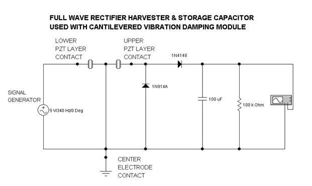
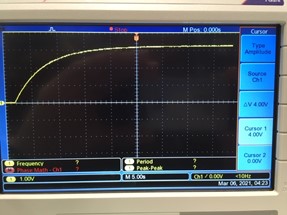
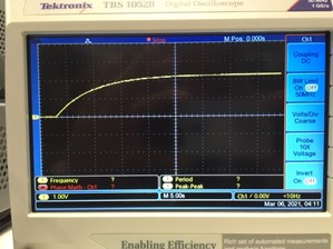
For an AC +/- 2.5 V @ 340Hz signal generator input to the VDM, lower PZT layer, the resulting DC voltage across the 100kOhm load resistor was 2.24V DC ( 50.2 microWatts). At 335 Hz, the resullt was 3.24V (105 microWatts). It took about 25 seconds for this harvester system to reach equilibrium with the drain of the 100kOhm resistor.
NOTE:
The 100kOhm resistor value chosen here was picked at random, and does not represent the optimum value. The circuit is also not the most effective, but there is no "best circuit." The job of finding out what works best for your application environment (i.e. vibration intensity spectrum) can be greatly facilitated by use of the VDM because any conceivable vibration profile can be applied to the lower piezo layer as a low power electrical signal.
Using a D/A converter (stand-alone, or as part of a LaBView or MatLab program) it is also possible to excite the lower layer directly from an acceleration data file taken from your actual vibration environment. It is really easy to obtain one of these files using one of Mide's pocket sized enDAQ sensor (just tape it down anywhere, push the button, wait a minute, stop it, and the file is ready to download by USB or from the cloud! Just remember to scale the final output voltage from your signal source per the G-per-Volt equivalence calibration.
Conclusion
The Vibration Damping Module, VDM for short, is clearly a very handy thing to have, both for hands on learning about piezoelectrics’ response to vibration and also for developing circuitry aimed at interfacing with piezo devices intended to be used in vibration environments. It is it’s own vibration source, largely eliminating the need for a shaker table. It has its own integral real time vibration amplitude sensor, eliminating the need for an accelerometer or deflection sensor to monitor the effects of modifications on vibration amplitude. It’s a "bolt anywhere vibration lab."
Finally, the VDM itself (just the piezo bimorph without the bolts & base) can be bonded to any object (like a beam) or surface (like a panel) and used exactly as above. And the module is its own scale-up kernel. If a single one is not powerful enough for the task, use lots of ‘em... we’ll make more!
For more, don't forget to subscribe to our blog and also check out our Resources page for video tips, webinars, handbooks, and guides. And, if you have any questions please get in touch with us at Piezo.com.
Related Posts:
- How to Safely Solder Joints onto Piezo Transducers
- How to Determine Resonance of a Piezoelectric Cantilever Beam
- Four Steps to Selecting a Piezoelectric Energy Harvesting Device