How to Determine Resonance of a Piezoelectric Cantilever Beam

A common question I receive is: At what frequency should I operate my piezoelectric device? There are many answers to this question, but for energy harvesting or actuation with large displacement there is only one answer: at resonance. Of course, the follow-up question is: What is the resonance of my part? This is a question that is hard to answer remotely, as resonance is affected by every part of the system. Luckily, there are a few simple experimental procedures that you can perform to determine the resonance of your piezo. In this blog I will give a quick overview of resonance and why it matters, then show you how to perform these tests yourself.
What is Resonance?
Resonance is the tendency of a mechanical system to respond at greater amplitudes when the frequency of oscillation matches the system’s natural frequency of vibration. The natural frequency (also known as resonance frequency) depends on many parameters of the system, particularly the stiffness (Young’s modulus), mass, and geometry. Resonance can be determined analytically, but these calculations can become quite complex when considering a system of composites and irregular structures. In this blog we will focus on determining the resonance of a simple piezo cantilever through experimental methods only.

Why is Resonance Important?
When driving a piezo cantilever, the largest deflections (with lowest power consumption) can be achieved only at resonance. Increased deflection comes at a cost of decreased force, but this compromise is often acceptable when maximum motion is desired.
When using a piezo for sensing applications, one must be aware of the resonance. Excitation of the piezo at its resonance will amplify the signal and can result in saturation and erroneous measurements. For this reason, it is wise to ensure that the system resonance frequency is not near the frequency range of interest when using piezoelectric sensors. On the other hand, operating at resonance is ideal for vibration energy harvesting.Resonance of an undamped cantilever
Method 1: Measuring natural frequency with an oscilloscope
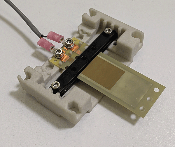
In this test we will subject a piezo cantilever to a small impulse then allow it to freely oscillate. Piezo materials can act as self-powered sensors, so we will monitor the resulting AC waveform to determine the resonance. The piezo and clamping kit are available for purchase on our website, but a similar procedure can be used for most any piezo and clamping scheme.
Materials and equipment used: Experimental Setup:- Clamp piezo at the “Zero” clamp line (6mm over the piezo)
- Connect cable to piezo contacts using the ring terminals
- Connect cable leads to oscilloscope probe (polarity is not important)
- Set oscilloscope to “Single” trigger mode
- Start oscilloscope
- Lightly flick the end of the piezo cantilever and allow it to freely oscillate
- Resulting waveform should be captured by oscilloscope and look like the following image
- Use the “Measure” function on your oscilloscope to determine the frequency of the waveform
- The measured frequency is the natural resonance frequency of the beam!
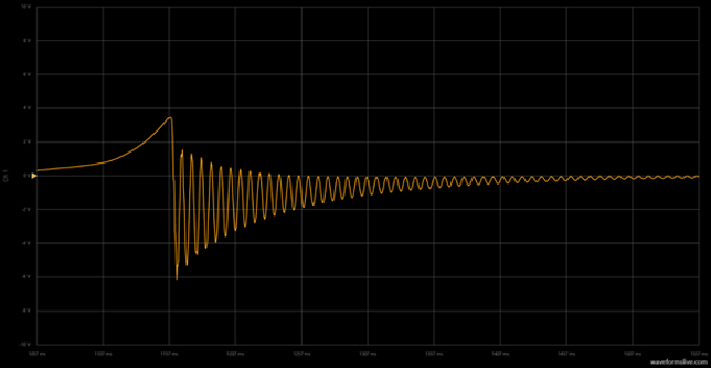 Figure 1: Oscilloscope capture of piezoelectric transducer output during experiment.
As you can see, finding the resonance of a piezo cantilever is quite simple. With just a single piece of common lab equipment you can perform this test.
Method 2: Driving a piezo with a function generator (no oscilloscope)
If you do not have access to an oscilloscope but are able to get your hands on a function generator (inexpensive models can be purchased for under $50), then this method is for you. These results will be less accurate, as they are based on visual observation rather than collected data but should provide a reasonable approximation.
Materials and equipment used:- S128-J1FR-1808YB sealed piezo bender
- KIT-004 Sealed Piezo Clamping Kit
- Function generator
- EPA-104 Linear Amplifier (optional)
- Clamp piezo at the “Zero” clamp line
- Connect cable to piezo contacts using the ring terminals
- Connect cable leads to function generator output (polarity is not important)
- Start function generator and set output to sine wave with an initial frequency below the expected resonance.
- Increase drive voltage until motion of piezo becomes visible.
- Optional: use a desktop amplifier if higher voltages are needed. 20-50V peak voltage should be sufficient for this test.
- Slowly increase frequency on the function generator. Observe the motion of the piezo cantilever. Amplitude of the vibrations will increase as resonance is approached.
- Continue increasing frequency until motion reaches its maximum. For a cantilever there should be a very small frequency range (~1Hz) where the amplitude is greatest. The center of this range is the resonance frequency.
Although less accurate, this simple and low-cost method is an effective way to determine resonance without using an oscilloscope.
Method 3: Driving a piezo with a function generator and monitoring with voltmeter
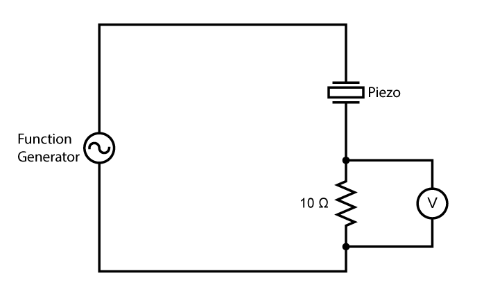
Like the previous method, this procedure uses a function generator to excite the piezo, but instead of using visual observations, a sense resistor with a voltmeter is used to find the resonance. When a piezo is operating near its resonance, the voltage drop across it is at its minimum. Therefore, a resistor in series will have the greatest voltage across it when the piezo is at resonance. With this knowledge we can use a simple circuit to find the resonance.
Materials and equipment used:- S128-J1FR-1808YB sealed piezo bender
- KIT-004 Sealed Piezo Clamping Kit
- Function generator
- 10Ω Resistor
- Handheld digital multimeter
- Assemble circuit as shown in following image
- Set digital multimeter to AC voltage measurement
- Start function generator and set output to sine wave with an initial frequency below the expected resonance.
- Set drive voltage to 5-10V.
- Slowly increase frequency on the function generator. Monitor the voltage across the resistor. Voltage should increase as frequency increases.
- Continue increasing frequency until the voltage begins to decrease again. For a cantilever there should be a very small frequency range (~1Hz) where the voltage is greatest. The center of this range is the resonance frequency.
Although it requires an additional piece of equipment, this method should provide more accurate results than the visual method. Additionally, a digital multimeter is a tool that anyone working with piezo should be sure to have on hand.
In Conclusion
I hope this article helps you effectively operate your piezoelectric device. Please feel free to leave a comment or ask a question. For more information, check out our piezo education guides and don't forget to subscribe to our blog for more great application and education posts.