In Part 1 (Power Ultrasonics History & Technology), I reviewed the concept of the property piezoelectricity in certain crystals such as quartz, and presented a quick sketch on the history of the development of sonar enabled by piezoelectric crystals. Dr. Paul Langevin, a renowned French physicist, is credited with inventing the ultrasonic transducer for submarine detection. His work is recognized by the naming of his invention as the Langevin transducer. Part 1 described the original invention and the modern version of the Langevin transducer.
I'll go over:
- The Tonpilz Transmission
- Tonpilz Transmission Designs
- Applications Using the Tonpilz Transmission
- Source for Assistance with Power Ultrasonic Designs
- Power Ultrasonics Series
By itself, the Langevin transducer creates mechanical motion. The transducer has plenty of power, but by itself does not lend itself to producing useful work. In Part 2, I introduced a transmission mechanism, the horn, which attaches to the Langevin piezoelectric transducer, the acoustic engine. The horn directs and amplifies the mechanical motion generated by the Langevin transducer allowing its energy to be delivered to the tip of the horn in a high velocity regime suitable for friction welding, cutting, and scaling among other applications. You could think of the horn as an acoustic lever.
In this final part, I will present a second transmission method, Tonpilz transmission technology. In contrast to the horn that leverages the Langevin’s energy into a high vibrational velocity tip for mechanical work, the Tonpilz transmission scheme is aimed at getting 100% of the Langevin’s output into broadcasting acoustic waves from one end and 0% off the other. This makes the Tonpilz type transducer ideal for energy efficient high intensity ultrasound sources.

The Tonpilz Transmission
While the Langevin transducer is named for Dr. Langevin, the Tonpilz transducer is not named after anyone. Instead, it is a contraction of two German words. “Ton” is German for tone and “pilz” is German for mushroom; together they make ‘the acoustic mushroom’. Figure 1 shows the Langevin transducer with a Tonpilz transmission; and, the assembly does look somewhat like a mushroom.
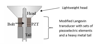
Figure 1. A modification of the Langevin transducer with the Tonpilz transmission – aka the acoustic mushroom
The essence of a Tonpilz design is two fold:
- Make the mass of the tail large in proportion to the mass of the head
- Flare the head so its surface area provides optimum acoustic power transfer to the medium
There are additional nuances to the Tonpilz scheme depending on whether it is intended to broadcast into liquid, solid, tank, or air, but here are the details of the basics:
The end of the transducer, the tail, is made of heavy metal such as steel or tungsten that provides an inertial ‘anchor’ for the piezo to work against. The assembly can have one to four (or even more) pairs of piezoelectric ‘donut’ discs. The addition of more piezoelectric discs creates a larger motion and more output power. The bolt holds the head and the tail together and also pre-compresses the discs to reduce the level of tension in the piezoceramic during the ‘stretch’ part of the transducer vibration cycle. The head is made of a light, low density material such as aluminum or titanium. As a result, the center of mass of the assembly lies toward the rear of the heavy metal tail area. A substantial portion of the energy generated by the expansion and contraction of the piezoelectric discs contributes to pushing the face of the head against an external medium. The flare in the head is adjusted to maximize the transfer of power into the medium, whatever that might be. This maximization is often referred to as ‘impedance matching’. Thus, the Tonpilz adaptation of the Langevin transducer is suited to designs for broadcasting powerful acoustic waves from the head into some medium, i.e. liquids, solids, tank walls, air, etc. as mentioned before.
Figure 2 animates the motion of the Langevin-Tonpilz assembly showing the large motion of the head compared with the minimal motion of the transducer back end. Figure 3 illustrates, with the yellow curve, the magnitude of the head motion compared with the motion of the transducer.
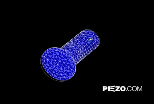
Figure 2. Simulation of the motion of the Tonpilz transmission on a Langevin transducer. The motion of the lightweight head is much greater than the motion of the heavy metal back end.
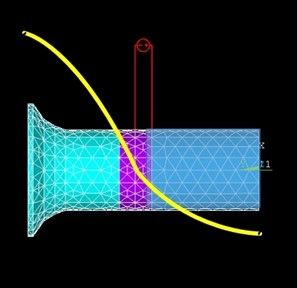
Figure 3. The yellow curve represents the magnitude of the horizontal extension of the head relative to the extension of the back end.
Tonpilz Transmission Designs
As with the horns, transducer-Tonpilz assemblies have a variety of designs. All of them have common properties. The back end is a different material than the head. The bolt secures the assembly. All the heads have a flare. There are numerous shapes and sizes of these assemblies as shown in Figure 4.
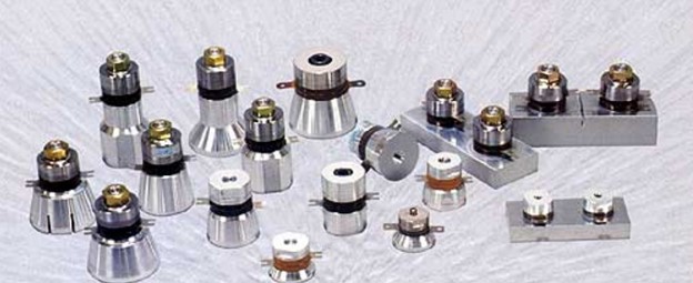
Credit: ultrasonic-resonators.org
Figure 4. A variety of Tonpilz assemblies
Applications Using the Tonpilz Transmission
One application in which the Tonpilz transducer-transmission assembly excels is its use in an ultrasonic cleaner. Some ultrasonic cleaners have piezoelectric discs glued permanently to the bottom of the tank. That construct works fine until a piezoelectric disc breaks. Replacement involves a time-consuming effort to chip off the broken disc, cleaning down to the metal, and bonding a new disc into place. Installing a new disc involves faith that another disc may not break soon so the whole process would have to be repeated. Fortunately, there is a better solution. The solution is the construction of ultrasonic cleaners with modular, replaceable piezoelectric elements which can be bolted and unbolted from the assembly. Figure 5 shows an ultrasonic cleaner module and a cross-sectional view of an assembly having two piezoelectric discs, the bolt, the heavy metal back end and the lighter metal, most likely aluminum, head. This is bolted to the bottom of the cleaner tank.
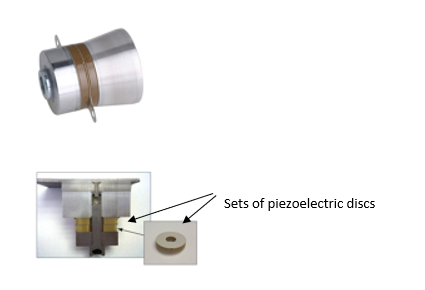
Figure 5. Tonpilz ultrasonic cleaner module and a cross-sectional view (below)
The second application for the Tonpilz transmission assembly takes us back to the application which lead to the development of power ultrasonics, sonar. A Tonpilz assembly can broadcast powerful sound waves for sonar applications. Figure 6 illustrates a Tonpilz sonar generator. The back end is both large and very heavy. It, therefore, has a large mass. Between the back end and the head are a large number of piezoelectric discs which can create powerful motion. With the lightweight, low mass head, the conservation of momentum results in high velocity motion of the head along the horizontal axis of the assembly. The assembly is encased in a waterproof, silicone rubber boot for immersion in water. The ‘tail’ in this case does not see the water, just the air in its compartment into which is broadcasts very little energy (i.e. it is a poor impedance match which in this case works to advantage).
The Tonpilz transmission assembly is both very effective and energy efficient. Many sizes of this tubular assembly are available for different sonar applications.
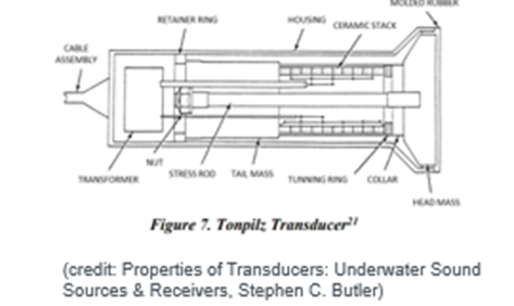
Figure 6. Tonpilz transmission assembly for use in sonar. Note the large number of piezoelectric discs.
Here is an alternative design for a sonar transmitter, one of my favorite designs. It is called the “shared tail mass Tonpilz transducer.” See Figure 7. This unique design was developed at the University of Texas in Austin. Each transducer has a long stack of piezoelectric discs. Each head has a large transmission area. The assemblies are arranged in a circular array, and they share a large mass on their back ends. When all the transducer –Tonpilz assemblies are operating in phase, pushing at the same time, their thrusts in opposite directions balance out and the shared tail essentially acts like an infinite tail mass. The net result is that this system broadcasts powerful acoustic waves radially outward from the center in a uniform 360 degree pattern. Very little energy is transmitted in the vertical plane. This design is excellent for a 360° scan of underwater surroundings. It is a creative design using the Tonpilz scheme.
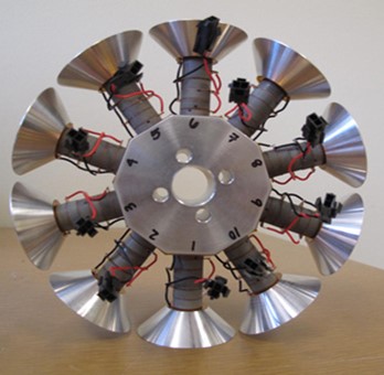
Credit: texasacoustics.org, University of Texas, Austin
Figure 7. The shared tail mass Tonpilz transducer with 10 transducer–Tonpilz assemblies arranged radially around the back end. The assembly generates an omni-directional planar broadcast pattern.
Source for Assistance with Power Ultrasonic Designs
This completes my discussion on power ultrasonics technology and its applications. For more information or assistance with power ultrasonic designs, visit us or contact us at www.piezo.com.
Power Ultrasonics Series
Part 1. Power Ultrasonics: Its History and the Technology
Part 2. Horn Transmission and its Applications
Part 3. Tonpilz Transmission and its Applications