In my previous blog (Power Ultrasonics History & Technology), I introduced you to piezoelectric concepts and the history behind the invention of piezoelectric-based ultrasonic transducers. I presented the Langevin transducer and how it worked. In current applications the transducer is not used by itself, but rather is a vibratory ‘engine’ used to drive various devices. Figure 1 reviews the Langevin transducer. The transducer is effectively a longitudinal resonator consisting of sandwiching piezo elements between two metal cylinders and secured with a center bolt. High AC voltage supplied to the electrodes in contact with the piezoelectric discs provides the excitation energy which causes the piezo discs to push and pull the metal cylinders along the axis.
- A Horn as the Transmission for the Engine
- Horn Designs
- Applications for Ultrasonic Transducer-Horn Assemblies
- A Second Transmission Technology
- Power Ultrasonics Series
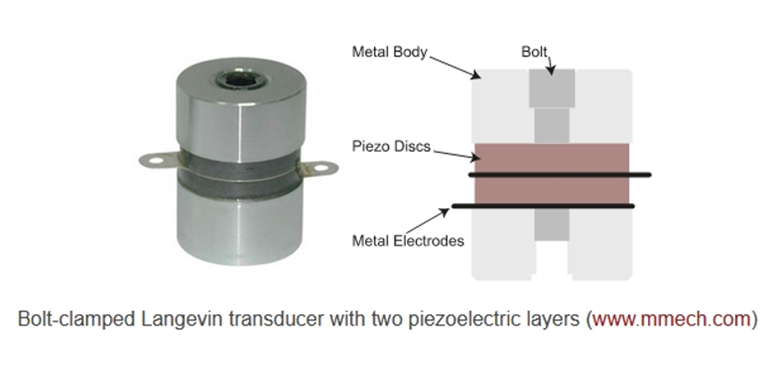 Figure 1. Example construction of a Langevin piezoelectric transducer, a mechanical engine
Now I need to introduce you to the methodology that will allow the transducer to serve useful applications.
I had described the transducer as a source of mechanical power, an engine. Just as an automobile engine needs a transmission to deliver the situationally correct amount of power to the road, the Langevin transducer needs a transmission to direct and focus its power output to its load.
The ideal transmission must do two things:
- The end faces of the Langevin transducer are pistons that move in opposite directions along the axis at ultrasonic frequencies. Nearly 100% of applications need to transmit ultrasonic power in one direction (not two). So as much as possible we’d like to trick the transducer into emitting the majority of its energy in one direction.
- By design, the transducer will produce the desired amount of acoustic power output, however nearly 100% of applications require that the power be brought to bear on a load (or ‘target zone’) that’s a different size than the piston faces.
Both of these goals can be achieved using a construction commonly known as an ‘ultrasonic horn.’

A Horn as the Transmission for the Engine
The output power from a Langevin transducer can be focused down on a smaller area by coupling it to a tapered metal extension referred to as an ‘ultrasonic horn.’ The horn acts as a mechanical transformer, analogous to an electric transformer. As a transformer converts a voltage from an input level to a higher or lower output level, the horn transforms the low velocity - high force input of the Langevin engine to a high velocity - low force output at the tip of the horn. Effectively the horn acts as a half-wave resonator connected to the Langevin half wave resonator, joined at the center of vibration to make a free space full wave resonator. The principle causing the amplification is the conservation of momentum. Unlike the Langevin transducer, the horn has a heavy end (where it joins the transducer) and a very light end. Vibrating in free space, the momentum of the heavy end of the horn (heading left say) must be equal and opposite the momentum of the light end (heading right). Therefore, the velocity of the tip has to be high enough to balance the equation.
Figure 2 shows a tapered horn attached to an end of the Langevin transducer. Above the diagram of the transducer-horn assembly is a curve showing the displacement of the assembly along the horizontal axis as the piezoelectric discs expand and contract. The tip of the horn has the largest displacement.
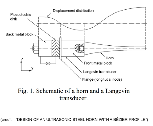
Figure 2. Diagram of a Langevin transducer and a horn with the displacement curve showing the amplification of the motion of the tip of the horn compared with the motion of the transducer on the left
The shape of the horn determines the quantity of motion amplification. Figure 3 shows three designs for horns along with amplification curves. The step horn achieves the highest velocity amplification which translates into the highest motion amplification. Figure 4 demonstrates the movement of the tip of a step horn. The animation shows how much the tip of the horn moves relative to the movement of the transducer, the other end of the assembly. Figure 5 shows the results from a finite element model simulation of a step horn amplified Langevin transducer. The yellow curve provides a quantitative illustration of the magnitude of motion which could be observed (with a microscope say) all along the surface of the step horn assembly. The motion gain in this example is about XXXX %
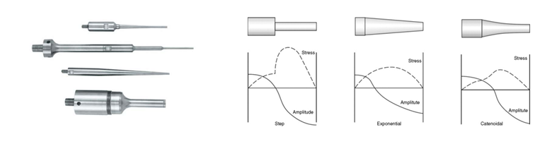
Figure 3. Three different horn designs and their motion amplification curves
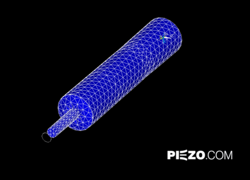
Figure 4. Illustration of the motion of a Langevin transducer-step horn assembly
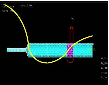
Figure 5. Representation of the horizontal motion of the assembly as a connection of two half-wave resonators
Horn Designs
Because the only real rule for horn design is conservation of momentum, there are a huge variety of horn shapes and horn tips. Examples of the myriad styles of horn shapes with different tips are shown in Figure 6. The far-right horn, for example, is an assembly of multiple horns attached to one transducer. Each shape has a unique purpose. Each design converts the vibration at the face of the Langevin engine to a vibration on the face of the tip of the horn. The geometrical design of the horn tip provides a cross sectional shape and motion designed to accomplish a specific task.
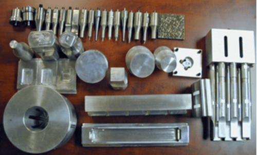
Figure 6. Variety of horn and tip shapes for performing specific tasks
Applications for Ultrasonic Transducer-Horn Assemblies
Let me give you some examples of uses of the high motion, high energy, mechanical power concentration output coming from the tip when a horn is attached to a Langevin transducer engine. The applications are wide-ranging.
The step horn with the Langevin transducer can make ultrasonic plastic welders and ultrasonic metal welders. Figure 7 shows an example of an ultrasonic welder. The vibration of the horn forces the two pieces that are to be welded to rub against each other at a high rate of speed creating a tremendous amount of heat. The temperature rise melts the plastic. Metal pieces are not melted, but the ultrasonic welder creates a “friction weld.” An example of the use of a friction weld is the process for attaching electrodes to solar panels.
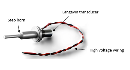
Figure 7. Ultrasonic welder for plastics and metals
Other machining applications include cutting operations with a wide range of cutting tool tips as shown in Figure 8. Ultrasonic cutting tools work well for ceramic materials. The cutting tool bears down on the surface making contact to the ceramic material via the particles in a slurry of material containing abrasive grit. The tip grinds through the material creating the desired shape.
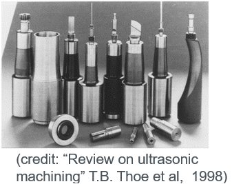
Figure 8. Example ultrasonic cutting tools
In the application shown in Figure 9, the tip of the horn is a knife. The ultrasonic knife cuts through composite materials made with carbon or glass fibers very readily. Another version of this type of ultrasonic knife is used in surgical applications. The value of the knife is not its cutting quality but its ability to quickly cauterize tissue by the friction of the blade against the flesh, resulting in minimum blood loss and lower tissue trauma.
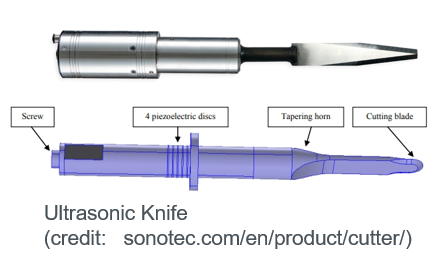
Figure 9. Example ultrasonic knives for cutting composite materials and for medical surgery
Another use for power ultrasonics on humans is the dental scaler shown in Figure 10. The dental scaler is an effective tool for dental health. The dental scaler uses high frequency tiny vibrations at the tip to scrape plaque off teeth. I can hear the high pitch scaler piercing through my head now.
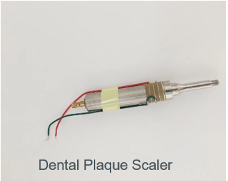
Figure 10. The ‘guts’ of the ultrasonic scaling tool used in dentistry
Thinking about the ultrasonic surgical knife and the ultrasonic dental scaler makes me a little queasy so let’s switch back to another industrial application for horn transmission technology. Figure 11 shows a flow-through version of the Langevin transducer-horn assembly. Liquid flows through the middle of the assembly and is insulated from the piezoelectric ceramic elements and the high voltage wiring. The small disc on the tip of the horn resonates at the same frequency as the piezoelectric ceramic discs. Liquid coming out of the disc is subjected to this high rate of vibration and is instantly converted to a spray of droplets. The coating industry uses this technology in automated painting machines.
Next Topic, a Second Transmission Technology
Those are some of the applications for power ultrasonics. We concentrated on the applications for the horn transmission element and saw that there are numerous designs for horns. In my next blog, I will discuss another transmission technology and its applications.
For more information visit www.piezo.com.
Power Ultrasonics Series
Part 1. Power Ultrasonics: Its History and the Technology
Part 2. Horn Transmission and its Applications
Part 3. Tonpilz Transmission and its Applications