Piezoelectricity and its Applications in Power Ultrasonics
The first time I became fascinated by power ultrasonics was when creating ultrasonic acoustic sources so powerful that they could levitate themselves on a cushion of air. I've been hooked ever since.
It's with this in mind, that I've put together the Power Ultrasonics Series; to expose people to the power and possibilities of ultrasonics especially when implemented with piezoelectric materials.
The ‘piezoelectric effect’ describes a phenomenon exhibited by a few crystalline materials in which they produce an electrical charge when subjected to mechanical stress, i.e. squeezed. The sign of the resulting voltage changes if compression crosses over to tension. For historical reasons this is referred to as ‘the direct piezoelectric effect’. The phenomenon is reversible. For these same materials, forcing a charge onto their surface via applied voltage will cause them to mechanically expand or contract. This is referred to as ‘the converse piezoelectric effect’. As with the direct effect, the direction of crystal distortion (i.e. expansion or contraction) will follow the plus or minus sign of the applied voltage.
- Abbreviated History of the Development of the Ultrasonic Transducer
- Langevin’s Creation
- Modern Langevin Transducer
- Making the Transducer Useful
- Power Ultrasonics Series
The converse piezoelectric effect is what makes power ultrasonic devices possible. While natural crystals exhibit piezoelectricy, quartz being the prime example, artificial crystals can exhibit much higher electromechanical conversion effectiveness and are exclusively used for the power ultrasonics we will discuss. Lead zirconate titanate compounds in ceramic form are by far the most commonly use for devices currently in use.
An AC voltage applied to a piezoelectric crystal will cause it to expand and contract in response. The expansion and contraction can create sound pressure waves or otherwise act on adjacent media. For practical use, piezoelectric crystals are bolted, bonded, soldered, or otherwise incorporated into composite ultrasonic transducers with the right geometry to convert the applied AC voltage into useful vibrational energy.
Piezo-driven ultrasonics have low power and high-power applications. Examples of low power applications include medical devices for imaging internal organs or structures such as heart valves and fetuses and clock signal generators in electronic instrumentation. We will focus on the high-power application including sonar, flow metering, underwater communications, ultrasonic drills, ultrasonic cleaners, friction welding, cutting blades, dental scalers, and fluid atomization.

Abbreviated History of the Development of the Ultrasonic Transducer
Let me introduce you to the history of the discovery of piezoelectricity and ultrasonic transducers. The brothers, Pierre and Jacques Curie, are credited with the discovery of the piezoelectric effect. They published a paper in 1888 reporting on the measurement of the piezoelectric effect in natural crystals. Initial applications were limited to an electric scale used for demonstration purposes and a sensitive, picoampere current source used by Pierre’s wife, the famous Marie Curie, for radiation studies. These two devices were passive devices as the development of electronic amplification technology was at least two decades in the future. Without vacuum tubes or transistors, circuitry was not available to provide the AC drive signals which could generate useful vibration from the crystals, and the subject of piezoelectrics remained largely academic.
World War I created the stimulus for ultrasonics research. US and European allies had an urgent need for countermeasures against successful German submarine attacks upon allied shipping.
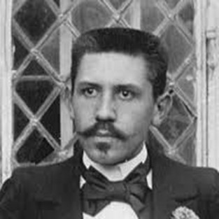 The hero of our story is Dr. Paul Langevin, a renowned French physicist, an expert in paramagnetism, secondary x-rays and the behavior of ions. See Figure 1. Dr. Langevin had performed his doctoral research under Pierre Curie. He was a contemporary of many of the other famous physicists of the early 20th century including Albert Einstein whose theory of relativity Langevin supported.
Figure1. Dr. Paul Langevin, renowned French physicist and a handsome man. (He had an affair with the widowed Marie Curie. Physicists can be lovers too, and not just French physicists.)
In 1915, the French government received a proposal from a Russian scientist, M Constantin Chilowsky, who suggested using electrically induced magnetic attraction to produce high frequency oscillations for creating high frequency waves in water. This may seem surprising to you; but, at that time, France and Russia were allies. The French government gave the proposal to Dr. Langevin. He had Chilowsky join him and created a team to study Chilowsky’s proposal at the School of Physics and Chemistry in Paris. The team’s goal was to develop a practical method for creating an intense pulse of high frequency sound, and their work resulted in a patent (granted in 1923) which detailed the use of electrostatic and magnetic means to broadcast and receive acoustic signals under water.
After that Langevin, drawing on his experience with the Curies, continued on experimenting with piezoelectric crystals to create the energy for generating sound waves.
While other allied teams explored different approaches, Dr. Langevin’s team demonstrated a practical working device. The Langevin team combined newly available vacuum tube circuit technology with natural quartz crystals to create a powerful ultrasonic device capable of echo detection of the presence and depth of an underwater submarine. Because the war ended prior to the final convincing demonsration of the device it was never deployed for anti-submarine warfare in WWI, however it set off a world-wide development effort to develop and manufacture sonar equipment for military use.
It is interesting to note that Langevin’s work culminated in a 1920 patent application for a piezoelectric sonar device. Due to the high level of national and financial interest in controlling this technology other groups contested the patent, and the US patent office did not actually grant the patent until 1941, 21 years later. We now know Langevin’s technology as sonar.
Langevin’s Creation
Let’s take a look at Langevin’s original device as shown in Figure 2. It embodies the foundational insight that enabled the applications for ultrasonics. He sandwiched a quantity of 10 cm x 10 cm x 1.5 cm quartz crystals between two ¾ meter diameter steel plates. A hardened glue held the sandwich together. Langevin’s team applied a high AC voltage, of magnitude around 3000 V between the two steel plates. The frequency of the AC voltages stimulated the crystal-plate structure at its resonant frequency which was around 33 kHz. The AC voltage induced an oscillating electric field in the quartz crystals which expanded and contracted vertically pushing and pulling the steel plates. The movement of the crystals created a large area, high-power sound wave. The plate in contact with water transmited the sound wave. This transducer could also serve as the receiver of the reflected sound wave, or a separate transducer could act as the receiver to complete the submarine detection system.
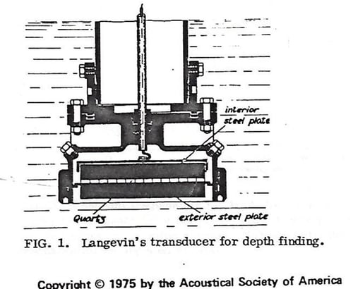
Figure 2. The Langevin transducer. The high voltage is applied at the top of the center tube and is connected across the two steel plates. The exterior plate, in contact with water, transmits the pressure wave.
Modern Langevin Transducer
The term “ Langevin transducer” now describes any piezoelectric-driven longitudinal resonator based on sandwiching piezoelectric materials between two plates secured by a center bolt. Figure 3 shows a modern Langevin ultrasonic transducer. The components of the transducer perform the following functions:
- The transducer has two layers of piezoelectric discs. Use of two piezoelectric discs allows the outer metal cylinders to be at ground potential which protects personnel from shock hazards and minimizes the risk of a short circuit. The discs are placed such that their polarities are opposite to each other; and that allows applying high voltage only to a single location, a center conductor that is sandwiched between the two piezoelectric discs.
- The bolt provides precompression on the piezoelectric discs. Piezoelectric materials can fracture easily from tensile stresses of around 2,000 psi, but their compression strength can withstand a five times greater pressure of 10,000 psi. The bolt bias the discs into their compression region. Thus, when the discs vibrate, their motion is from full compression to a small amount of compression and they never see destructive tension. The Animation in Figure 4 illustrates the motion of the transducer.
- The end plates distribute the point force of the bolt over the entire piezo surface so that the both the static and dynamic compressions in the piezo material are uniform through its volume.
Figure 5 shows how textbooks represent the Langevin transducer. The books describe a half-wave resonator with standing wave motion. The two ends move with equal amplitude in opposite directions while the center of mass does not move. The yellow line represents the magnitude of the transducer’s right and left motion.
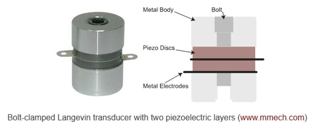
Figure 3. Modern Langevin transducer
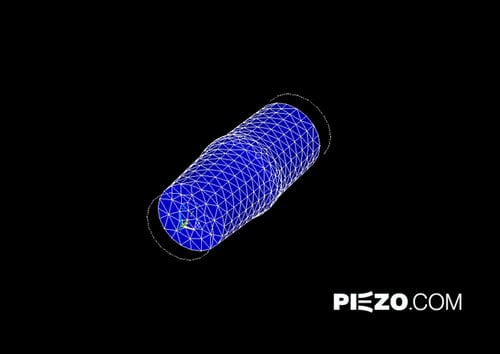
Figure 4. Animation of the vibration motion of a Langevin transducer
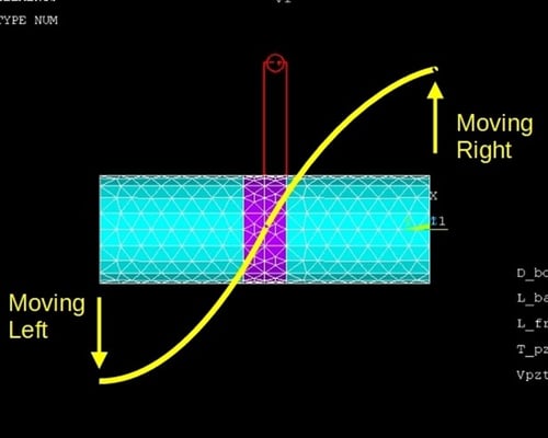
Figure 5. Langevin transducer described as a half-wavelength resonator with standing wave motion. The yellow curve represents magnitude of the transducer’s motion at each end.
Making the Transducer Useful
By itself, in isolation, the transducer has limited applicability. Generally the objective of any ultrasonic implement is to apply vibration or sound in one direction; however, the raw motion of the Langevin transducer at both ends. Thus the full energy output of the piezoceramics cannot be brought to bear on a target.
If you think of the transducer as an engine, a source of undirected power, then in principle a transmission mechanism might be constructed to direct the full output power of the piezoceramics in one direction, toward a useful end - exactly in analogy to a car engine and transmission. Just such combinations of transducer engine and transmission mechanisms enable the applications we mentioned earlier. The transmissions are all vibratory instead of rotary and they are quite interesting. In the next two parts of this 3-part series I will present the characteristics and the applications of two transmission methodologies, the ultrasonic horn transducer and the Tonpilz transducer.
Learn more at www.piezo.com
Power Ultrasonics Series
Part 1. Power Ultrasonics: Its History and the Technology
Part 2. Horn Transmission and its Applications
Part 3. Tonpilz Transmission and its Applications