We recently got an interesting question about maximizing power output from piezo harvesters:
Our required output: 200 mA rms @ 5V rms
Our available vibration: 3 G's rms @ 25 Hz
How many of which Piezo.com part would it take to supply a 200 mA steady state current?
What follows in this post is not a "how to" explanation for obtaining an answer, but rather a description of the process we used to answer this question. It can be considered an outline of how this question could be answered in either analytical or experimental fashion.
- Choosing a Bimorph Part
- General Approach to Determining the Maximum Power Output
- Determining Tip Weight
- Determining Electrical Load
- What Part Can Supply a 200 mA Steady State Current?
- Scaling Up to 200 milliamperes
- Conclusion
Choosing a Bimorph Part
That's a lot of current. We know that the number of parts will be high, so we start with the largest standard bimorph generator that is easy to mount.
Because we know the customer is interested in current rather than voltage output, we specify that the plates be "Y" polarized (i.e. poled for parallel operation).
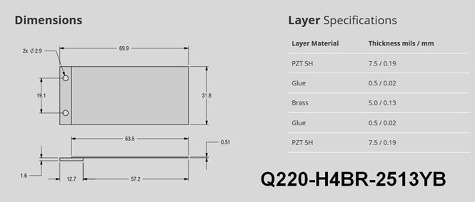 Q220-H4BR-2513YB: The largest standard bimorph part
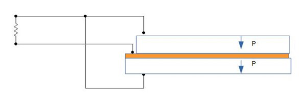
"Y" poling arrangement gives maximum current output
So now we will describe the steps used to optimize the output of this single bimorph at the target operating point, and then see how many of these parts it takes to scale up to 200 mA @ 5V DC
General Approach to Determining the Maximum Power Output
How do we actually determine the maximum power output for this part, mounted and driven as specified? Power output is proportional to drive frequency and varies as the square of the average strain in the piezoceramic. The frequency is fixed by the circumstance of this example, but the strain is not.
While cantilevered bimorph is being driven, there is a region of maximum strain near the cantilever point (i.e the base or clamping point). Maximum output for the simple cantilever is reached when the value of that maximum strain at that site is at the highest value which can be indefinitely endured by that bimorph’s ceramic – i.e. it’s fatigue limit, which is approximately 500 microStrain (500E-06). At that point the average strain in the ceramic is considerably lower than that maximum value; however, driving it any harder will only result in the formation of fractures at that site and premature failure.
So the design goal is to ensure that 3 G’s rms / 25 Hz drive results in 500E-6 Strain at the base of the cantilever.
There is not really an easy-to-use formula for getting the answer. If the bimorph were driven with no electrical load (i.e. zero current drawn out during operation), the 500E-6 Strain point could be easily estimated using beam theory and the bimorph’s dimensions along with its material elastic and mechanical loss properties. But when we add in the electrical power draw, that has the effect of damping down the vibrational amplitude, thus reducing the strain at the cantilever point and increasing the allowable drive level.
Getting the answer involves dialing the value of strain & electrical load into balance. Formulas for doing this do exist, however they are too complex to cover here. So we’ll describe this as an empirical procedure which could be (and most often actually is) followed in the laboratory. We are going to "pretend" that we know all the properties of all the materials in the bimorph, and that we can accurately and repeatably:
- control the bimorph’s base excitation
- adjust its resonant frequency by means of adding masses
- observe its motion, surface strain at the cantilever point
- and extract electrical power with resistors whose value we can adjust to obtain the aforementioned balance.
We will do the empirical optimization using a Finite Element Model (FEM) of the harvester system (bimorph, excitation, resistor).
The only thing the FEM really saves vs actual experiments in the effort of getting a performance estimate is the frustration of making adjustments in one thing only to find out that inadvertently a second parameter got adjusted, or discovering scatter in the results while attempting repeat measurements, or the worst: breaking the bimorph and having to start over. Obtaining that estimate by means of a model yields both a good starting point for the eventual inevitable experiments and a map for how to get there.
Determining Tip Weight
First thing we do is toss the bare cantilever on a shaker table set for 25 Hz and carefully ramp up the drive amplitude to 3 G's rms ( 4.23 peak G's). We find that the beam vibrational motion at the tip looks low, and the surface strain at the cantilever base is nowhere NEAR 500E-06. We now know we have to add some mass to the tip. This has the effect of lowering the resonant frequency of the beam closer to the drive frequency, and thus raising the vibrational amplitude and strain level.
Using our FEM (finite element model) which approximates the structure and materials of this bimorph, we place a point mass at the exact tip of the free end of the cantilever.
NOTE: in any real experiment, this is not possible – real masses are 3D distributed masses and do not behave like point masses. By completing the initial estimate this way, we eliminate model complexity and difficulties that have no bearing on the basic question.
First, we find out that if we put a tip mass on the bender so it resonates at 25 Hz, it reaches its recommended maximum surface strain of 500 E-06 at only about 0.5 G's. To avoid instant failure at 3 G's, we will have to add a lower tip mass such that the max surface strain operating point is reached at 3G's and 25Hz. This is actually a good piezo generator situation because slight variations in drive frequency will only change the electrical output slightly. Piezo generators designed for operation at resonance can put out high power at low G drives, but they have a very narrow frequency range in which they produce full power output, so output power falls off steeply (as in an order of magnitude) within a few Hertz of the peak.
Next, we empirically adjust the point mass from zero upward until the worst case strain on the surface is close to 500 microstrains at the 3 G / 25 Hz operating point. The mass turns out to be around 10 grams.
Determining the Electrical Load
As we mentioned, the electrical output (voltage, current, power) of this single bimorph module also depends on the electrical load that it must supply. That load might be a rectifier & storage battery, supercapacitor, AC-DC converter with a voltage regulator, microprocessor circuit, a simple light, or… well, anything. The bimorph and the load interact, so you have to determine both of them to define the energy that flows. For an estimate like this, it is expedient to assume that the load is a simple resistor. (Any other electrical load can be modeled as an equivalent resistor, so this actually does not limit the usefulness of our conclusions in any way.)
If we start with the resistor value being really high (like 100 megOhm), we will see that the output current is nearly zero, but the voltage is quite high compared to 5V target. To obtain the output current for this part, we effectively adjust the resistance value down and down until we reach the point at which there is 5V rms across it at 3G's rms, 25 Hz base excitation. Experimentally, this can be done with just a variable resistor in about 10 seconds, or it can be calculated analytically which takes a whole lot more time (papers are still being written about picking the best resistor) and is too involved to go into here. In the FEM, we now make trial & error adjustments to BOTH the resistor and the tip mass until we get 500 microstrains at 3G's rms / 25 Hz (remember, they interact). The resistor turns out to be 2500 Ohms (so at 5V rms the current flow will by (5 V)/(2500 Ohm) = 2 mA rms).
What Part Can Supply a 200 mA Steady State Current?
Here is our conclusion regarding a single part:
When shaken at 3 G’s rms / 25 Hz , the Q220-H4BR-2513YB will put out maximum current of 2 milliamps rms through a 2500 Ohm resistor when equipped with a 9.5 gram tip mass. Since its surface strain is approximately 500E-06, we anticipate to have a very long service life.
Scaling Up to 200 Milliamperes
200 mA can be obtained by summing the output currents from 100 of these parts. This is a large number, and in practice when actually mounted with real tip masses they WILL NOT ALL HAVE EXACTLY THE SAME RESPONSE to the excitation. They will have slightly differing amplitudes and slightly different phases. Consequently, if we choose to simply wire them up in parallel, at any given instant the ones at higher potential will be sending currents to the lower ones... but not to US here outside! In order to sum the outputs, the output of each part must must be rectified individually before the parallel wiring is made. This is the circuit arrangement most commonly used for adding piezo harvester outputs:
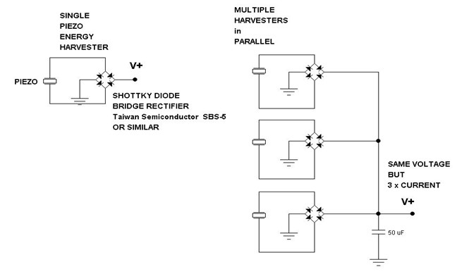 Summing power output from multiple piezo harvesters
NOTE: There will be a loss of 0.5 to 1.0 Volts of the output voltage as the current flows through the diodes when this scheme is used, but the output current can still be achieved.
Conclusion
Now you have to be saying to yourself: "That's ridiculous! Isn't there a way to get around using 100 parts to get 200 mA @5V ????"
The answer is: "Yes! Three "no brainers'":
- Mechanically multiply the available (low) environmentally available frequency to a higher piezo excitation frequency. Power output at max strain is proportional to frequency.
- Look at ways of distributing strain more evenly in the ceramic.
- Abandon the cantilever bimorph that utilizes the transverse 'd31' piezo coefficient in favor of a more complex mechanical design that utilizes the direct 'd33' piezo coefficient
Future blogs will examine some examples of these harvester strategies, but remember that "no brainer" does not mean "no effort."
For more, don't forget to subscribe to our blog and also check out our Resources page for video tips, webinars, handbooks, and guides. And, if you have any questions please get in touch with us at Piezo.com.
Related Posts:
- Using a Piezo Bimorph with Feedback for Vibration Control and Energy Harvesting
- How to Determine Resonance of a Piezoelectric Cantilever Beam
- Four Steps to Selecting a Piezoelectric Energy Harvesting Device