Synthetic Jets - Basic Principles

I see a lot of innovative materials and applications working in the field of smart materials. One technology I find very interesting is synthetic jets. These devices are particularly exciting due to the fact that they are in the process of transitioning from research to application. Scientific breakthroughs and advancements in miniature electronics, efficient power supplies, low power sensors, computer modeling, and prototype testing have enabled work with synthetic jets to progress in recent years.
In this post, I provide a very broad overview on synthetic jets including what they are, how they work, how they are constructed, and how they are used by both researchers and in nature.
Types of Synthetic Jets
A jet is a stream of fluid (such as air or water) that is created when the fluid travels through an orifice and into a medium of lower momentum. We encounter jets in our everyday life such as when you blow on something to cool it off. The jet of air is forced out of your body from your lungs and mouth as it enters the atmosphere. The resulting stream of air is directed primarily in one direction. This behavior can be leveraged in many different ways.
Unlike a conventional jet that typically has a compressed fluid source or combustion to create a thrust force, a synthetic jet is a periodic jet that is composed of surrounding fluid. The fluid is cyclically moved over a boundary, resulting in a net zero mass flux, but a significant momentum flux. As fluid is drawn from the surrounding area into an orifice, the fluid is pulled from all directions at a low velocity as shown in the animation below. When the fluid reverses direction and is forced back into the surrounding fluid, a jet is created. This jet has significantly higher velocity in a single direction, which results in a momentum that is much higher than was witnessed on the intake stroke.
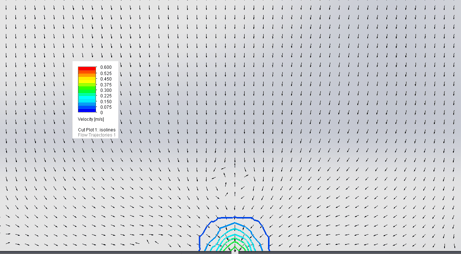

Fluid entering an orifice from all directions with a relatively low velocity shown with stream lines and velocity vectors (left) and particle animation (right).
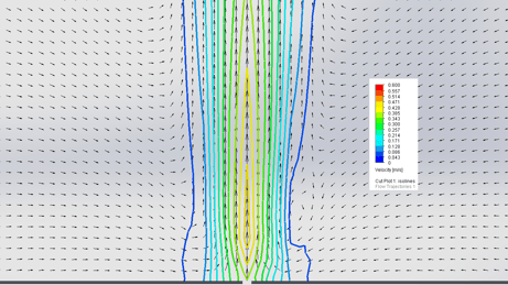

Fluid exiting an orifice in primarily one direction with a momentum higher than the medium it is entering shown with stream lines and velocity vectors (left) and particle animation (right).
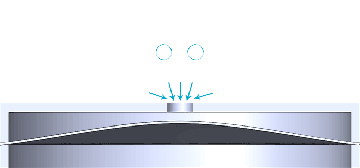
Fluid entering and exiting a controlled volume through an orifice. In this case, a flexible diaphragm creates the pressure differentials required to move the air.
Parts of a Synthetic Jet Actuator
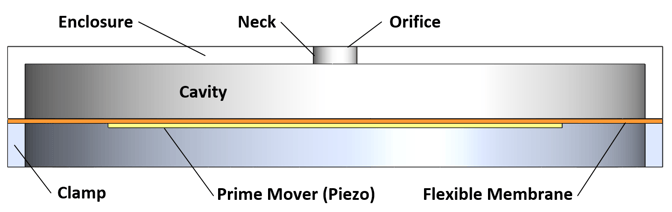
The creation of a synthetic jet requires several components that make up the synthetic jet actuator. Holding all of the parts of the synthetic jet actuator together is the enclosure and clamp. The enclosure is the main structure and is commonly made of aluminum or a polymer such as Delrin due to their low cost and machinability. The orifice is the hole is the enclosure that allows the fluid to move in and out. The orifice can be any number of configurations such as a circular hole, slot, or a series of holes.
As the surrounding fluid travels through the orifice it enters the neck. In its simplest form, the neck is the same shape as the orifice and is the thickness of the enclosure wall. At the other end of the neck is the cavity of the actuator. The cavity is the volume that temporarily stores the slug of fluid before expelling it. In order for the fluid to cycle in and out of the system, a flexible membrane is used that vibrates cyclically from a prime mover. The prime mover creates a mechanical input through a piezoelectric wafer, eccentric rotating mass vibration motor, or electromagnetic solenoid such as a voice coil. Alternatively, a reciprocating piston can replace the flexible membrane.
History and Applications
The term synthetic jets was originally coined by Ari Glezer, who did much of the early work on synthetic jets in the late 80s and early 90s with a focus on mixing and turbulence. He remains active in the community with recent publications focusing on synthetic jets for cooling and flow control applications.
The unique properties of a synthetic jet can be leveraged in many different ways, allowing them to be used in a wide variety of applications. General Electric has created a cooling system that they claim can be used to cool LED lights, cell phones, laptop computers, and other electronic devices.
The momentum of a synthetic jet can be leveraged to move the actuator as well as a small vehicle, as demonstrated by researchers at California Institute of Technology. Here the researchers are working on underwater propulsion similar to what is used by the nautilus, squid, and jellyfish.
Companies such as Boeing and Renault are conducting synthetic jet research as a flow control mechanism. Using synthetic jets to add momentum to the flow in specific areas reduces the boundary layer separation and results in lower drag. Lower drag results in lower fuel consumption and increased range. Additionally, the parameters of the synthetic jet can be modulated based on the vehicle’s performance and requirements. At low speeds, a sports car can have a light, moderately sized spoiler. At higher speeds, the same spoiler used in combination with synthetic jets could provide the performance of a larger, passive spoiler. The same approach can be applied to airfoils for lift.
Basic Design Considerations
While synthetic jets can be created many different ways, the most popular approach in literature and practice is using a piezoelectric bender as the prime mover. Piezoelectric devices can provide a lot of mechanical motion in a modest volume with a low power input, making piezoelectric based synthetic jets attractive in applications where size, weight, and power are constrained. Other popular approaches to creating a synthetic jet are oscillating pistons and electromagnetic actuators.
To minimize size, weight and power, an efficient synthetic jet is necessary. This will typically involve maximizing the momentum (or flow rate) of the jet. The flexible membrane will have a resonant frequency that depends on its particular geometry (diameter, thickness, material) driving it at this frequency will maximize its displacement. The cavity and neck should then be sized with a Helmholtz resonance close to that of the membrane.
There are a wide range of design parameters to work with. In order to start designing the full unit, the desired momentum or size envelope should be identified. With this, additional parameters can be chosen or calculated to maximize performance. Subsequent blog articles will guide the reader through the design process.
If you found this post interesting, and would like to stay current with similar topics, I'd invite you to subscribe to this blog. Otherwise feel free to leave a comment with any related queries.