How to Drive Piezoelectric Actuators
Authors’ Note: Jeff originally put this post together in 2016 to help people choose the best method for driving piezos, sharing his experience as an R&D engineer working on various applications for piezoelectric actuators. Michael made extensive revisions and additions to the post in July 2019 to add more technical details, explanations, and up-to-date references. For more in-depth technical information, see our Electronics Overview support article.
Operating a piezoelectric transducer as an actuator requires an electrical input, or driving signal, with certain appropriate characteristics. The two main components of the electrical input are the drive frequency and voltage amplitude. The frequency determines how fast the piezo will vibrate or change state. Both periodic (regularly repeating) and arbitrary signals can be used to drive a piezo, which corresponds to either continuous (vibration control) or intermittent (position control) modes of operation.
An example of intermittent control is a piezo controlling a valve that will typically have a state of “open” or “closed” indicating two discrete positions and change position as the valve needs to be opened or closed. Some examples of continuous control are a piezoelectric fan that operates at a constant peak voltage and constant frequency for its entire life, and a piezoelectric speaker that continuously changes the operational frequency to emit the desired tones. These example applications highlight the different driving needs that will be covered in this post. Most applications require an amplifier to increase the voltage of the driving signal to the high level needed to drive the piezo to the desired amplitude/displacement/position.
Considerations When Choosing an Amplifier
As amplifiers are evaluated for use with a system, it is important to understand the key parameters, and how they will affect the operation of the piezo. Knowing the following basic requirements will help facilitate the best amplifier selection. You also need to understand the key specifications of your piezoelectric device, specifically capacitance and drive frequency/voltage, as these impact the current and power you need from the amplifier. Our piezo products data sheet has all of the relevant information you need for the piezo actuator.
Output Voltage
Output voltage is the voltage range of the electrical signal that gets applied to the piezo, usually by an amplifier. Piezo amplifiers with an output voltage on the order of 100V to 200V are typical, and higher voltages are not uncommon for larger and more powerful actuators. If the actuator is meant to vibrate, it is common to require the unit to be driven to a negative voltage as well. Amplifiers will typically state an operational voltage range such as 0-200V or +/- 100V, for example. Most of the actuator products we provide are rated for +/- 200 V. Interestingly, a range of 200V and +/-100V are equivalent - see the section on DC Bias for the rest of the story. This is related to the signal amplitude, which is described either as peak (abbreviated pk), the distance from the midpoint to the highest point of the signal, or peak-to-peak (abbreviated pkpk or pp), the distance from the most negative to the most positive points of the signal.
Input Voltage
Input voltage is the voltage range for the driving signal. In order to drive a piezo through an amplifier, you need to put a signal into the amplifier, and the maximum voltage range of that input signal needs to be within the amplifier’s input voltage range. This is typically between 1V and 5V.
Output Current
This is the current output of the amplifier. Simply put, the amplifier’s maximum output current should be greater than the peak current draw of the piezo actuator. High voltage amplifiers will typically have a low output current (<1 A), but piezo actuators require very little current. For example, Mide's piezo fan draws about 5mA. A single amplifier will typically have enough power to drive multiple actuators simultaneously. Piezoelectric actuators behave like a capacitor, so the current draw is proportional to both voltage and frequency. PiezoDrive offers a nice calculator to determine the current draw of your actuator to help with choosing the proper amplifier. However, piezoelectric transducers will draw more current when driving at or near their resonance frequency which this calculator does not account for. Refer to the datasheet of the transducer to find its resonance frequency and characteristics.
Bridging
This feature allows one unit to be bridged with a second unit to increase the output current or maximum operational voltage.
DC Bias (Differential vs. Single-Ended Signals)
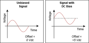 A DC bias is a flat offset voltage that exists in the driving signal that corresponds to the middle of the voltage range, or the default voltage when no signal is applied. This applies to both the input and the output voltage signals of the amplifier. The presence or absence of a DC bias relates to whether the amplifier is differential or single-ended. Typically, only single-ended amplifiers will have a DC bias, though they may not. This is because single-ended amplifiers only generate a single (positive) output voltage, with the other side of the piezo referenced to ground (held at 0V). For example, if an amplifier has a range of 0V to 200V then the middle of the range (and the DC bias) is +100V.
By contrast, a differential amplifier generates both a positive and a negative voltage that are symmetrical, for example, -100V and +100V, for a total of 200V of range. This means the middle of the range is 0V, so no DC bias. A bit more care must be taken when operating a unit with a DC bias, as the frequency response and resonance points will shift slightly (usually upward), compared to driving without DC bias.
Frequency
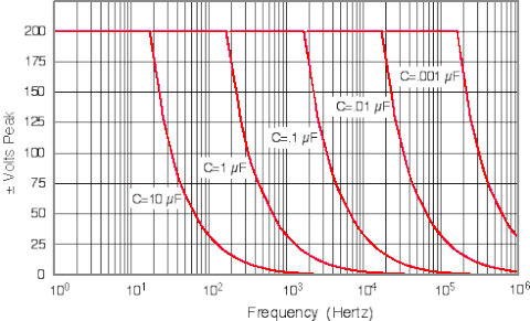
Simply stated this is the range of drive frequencies in which the amplifier can operate. However, this is often a common source of user confusion. In most cases the usable frequency is less than the stated absolute frequency and is limited by output power vs. capacitance of the load being driven. For example, this chart shows the different maximum voltage & frequency range combinations for different load capacitances for the EPA-104 amplifier from Piezo.com.
Voltage Gain
Voltage gain is the ratio of the output voltage to the input voltage, measured in volts per volt (V/V). Amplifiers operate based on the premise of scaling an input voltage to a higher voltage. This voltage gain is typically linear and fixed. When operating at higher voltages and near the limits of the equipment, the gain may not be linear and can indeed fluctuate with drive frequency, temperature, and other parameters.
Noise
This is the amount of electrical noise that may be experienced. Lower noise will typically cost more money and result in a more accurate output waveform. However, for many applications, small amounts of output noise may not be detrimental to the system.
Maximum Power
Even if an amplifier meets all of the above requirements for your application, it is important to keep in mind that it may not be able to meet all of the requirements at the same time! Amplifiers will spec a maximum power (in Watts) that can be supplied. This power will relate to the drive frequency, voltage, and piezo capacitance. In order for the amplifier to provide enough power to the piezo, it must be able to meet all of the requirements simultaneously.
This PiezoDrive calculator can help you determine if an amplifier will meet the power requirements of your piezo application.
Capacitance
This is the main electrical impedance characteristic of piezo actuators, and it determines the amount of current they draw. Most piezo actuators’ capacitance values range from 10nF to 500nF. Capacitance is an indicator of many key features of a piezo – piezos that are larger in size will have larger capacitances, as well as higher current draw for the same voltage signal, and usually a larger displacement, depending on the shape. In normal use, a given piezo’s capacitance will not change significantly. However, most of the common failure modes of piezos are accompanied by a significant loss of capacitance, which makes it a useful metric for detecting problems.
Connectors
Also called contacts, the type of connectors varies for both piezos and the driving devices. It can be surprisingly difficult to find the right connector and matching cable, so it pays to think ahead and plan out the connection path, both electrical and physical. For benchtop amplifiers, common connector types include BNC, banana jack, or screw terminal. Other types of drivers rarely have explicit connectors, so connection should be made through a circuit board (in the case of ICs), or directly soldering components together with wires (in the case of modules).
On the piezo side, there are two very common types of electrical contact. First is the bare contact, i.e. an exposed metal pad which is usually clamped or soldered to another metal surface or wire. Second is the “pig tail” wire, a nickname for an insulated wire with a short length of insulation removed from the tip. These connect well with screw terminals, and are easy to solder to circuit boards and other bare wires, or clip onto with test equipment such as alligator or hook clips.
Physically connecting a piezo to a larger system is a more complicated proposition and depends on the mode of actuation. For example, bending-mode actuators must be clamped to a rigid surface. See our article on Mounting Guidelines for more information.
Different Options to Drive a Piezoelectric Actuator
Piezoelectric actuators typically need to be driven by high voltage (on the order of 50V to 200V) to produce the desired amount of force or displacement. There are several methods to generate this voltage, and it is important to select one that suits your application. The methods and products discussed here cover a wide range of applications, but if you are still unsure what is appropriate for your system, feel free to reach out to us for help - Mide specializes in contract R&D for piezo applications.
There are several different types and styles of amplifiers available on the market. Choosing the correct one will depend on where you are in your development effort and what final requirements have been established. The following table provides a high-level overview of the amplifiers to be discussed.
|
Amplifier or Driver Type |
Relative Size |
Power Output |
Example Application |
|
COTS Integrated Circuits |
small |
low |
|
|
Amplifier Modules |
medium |
moderate |
|
|
Benchtop Amplifiers |
large |
high |
Research & Development |
|
DC Power Supplies |
varies |
varies |
|
|
Mains (Wall) Power |
small |
high |
|
|
Custom |
varies |
varies |
OEM solutions |
Benchtop Amplifiers

Benchtop amplifiers are often chosen at the beginning of a development effort due to their high performance. They function well over a wide range of frequencies (including DC) and voltages while producing a clean signal with minimal noise and distortion. This allows for the R&D activities to focus on the piezo’s performance and how it interacts with the rest of the system without worrying about the power supply and amplifier. The consistent and high performance does come at a cost. Benchtop amplifiers are often large, heavy, and power hungry. They may sacrifice electrical efficiency and generate significant amounts of waste heat to provide the user with the desired signal. When the performance of the system achieves desired levels, the amplifier can then be swapped for a more appropriate solution.
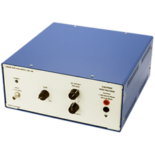
Piezo.com sells two options for benchtop piezo amplifiers. The EPA-104 is the larger of the two, with an output range of +/-200V and +/200mA, a frequency range from 0 to 250 kHz, and a maximum power output of 40W. This amplifier is great for driving larger piezos and arrays of multiple piezos, and the low noise characteristic means the driving signal will be clean and true to the original input. The wide frequency range also makes it good for driving ultrasonic actuators. The banana jack connectors on the output make it handy for clipping to exposed pads or pig tails for easy benchtop setup.
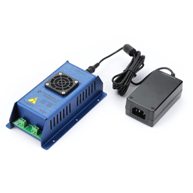 The EPA-008 is a more compact device, largely thanks to an external wall-adapter style power supply. With a voltage range of +/-180V and +/-30mA, it will drive most single piezo actuators just fine, and smaller arrays. The biggest trade off is the frequency range, which is limited to 1.5 kHz. This will not drive ultrasonics, but it will serve the vast majority of high-displacement piezo applications. The screw terminal connectors make for a nice clean setup, good for longer term demos or prototypes.
The PiezoDrive PD200 amplifier is a good example of a bench top amplifier. The unit offers a significant power output of 60W. Like the EPA-104, this is great for research and development work due to its reliable response and low output noise. One key difference is the BNC connections and mains power allow you to get up and running quickly.
COTS Integrated Circuits
Specialized piezo driver integrated circuits, also called ICs or chips, are the smallest way to drive piezos, allowing them to be incorporated into practical devices. A quickly growing market is haptics, which involves the application of force and vibration to communicate via touch to a user. Perhaps the most commonly used haptic solution is the vibrate function on a cell phone. Haptics has been traditionally dominated by off balance motors and linear resonant actuators, both based on electromagnetic technology.
Recently, piezoelectric actuators have become an appealing alternative thanks to higher energy efficiency, higher bandwidth, solid state technology, and control authority. Applications such as wearables and hand-held electronics require an IC / chip style amplifier due to size, weight, and heat rejection requirements. These ICs are directly integrated into the circuit boards of the device and normally run on an input of 3.3 VDC or 5 VDC. A significant limitation of chip based solutions is the maximum power output of the devices. Since the ICs are small, they don’t have the physical hardware required to generate very large voltages. Their size also limits the device’s ability to reject heat, requiring the output power of the device to be limited to prevent damage to the driver.
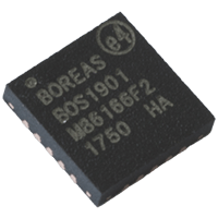
The latest entry to the piezo driver IC market is Boreas Technologies, with a focus on haptic applications. The major highlights of this solution are the low power consumption, small size, and ease of implementation. The BOS1901 chip has excellent energy efficiency – driving a piezo with 100nF capacitance at to 300 Hz takes 350mW. It has an output range of 190Vpkpk and an input voltage of only 3 to 5 VDC, well suited for small and medium-sized piezo actuators. The chip itself is only 4 x 4 mm in size and takes just 7 other discrete components for a total board area of about 15 x 15 mm. It also has a high-speed SPI digital front end for the input signal, which makes it great for incorporating into embedded electronic systems with minimal analog circuitry. This is one of the chips our company uses in haptics applications. For example, we now have a commercial development kit for wearable haptic piezo actuators that provides a jump start for research and development with piezo-haptics. The BOS1901 is available as single chip ($6) and in a development kit ($399).

Texas Instruments offers a pair of chip based amplifiers, which are likewise marketed at piezo haptics. The DRV2667 and DRV8662 are approximately 4 mm x 4 mm in size and operate on 3-5 VDC, with an output voltage range of 200Vpkpk. They are available in several form factors including the raw chip ($4), an evaluation board ($100), and even a custom breakout board ($28). Since TI is interested in selling chips and not full piezo driver systems, they offer a lot of reference designs that can be used to create custom electronics boards. User yurikleb on Instructables offers a tutorial to get the chip running with an Arduino.
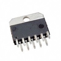
A higher power chip based offering is the Texas Instruments OPA2544. This dual opamp takes a wide range of input voltages (+/- 10 VDC to +/- 35VDC), is able to provide a maximum output of up to 4 amps, and has an output voltage up to +/- 70 V.
Since this unit packs so much power in a small package, it will be important to keep it cool during operation. Overheating can reduce the output current or even cause it to fail. This unit costs approximately $24 in low quantities. At these power levels, the unit can operate Mide's piezos around 20 kHz. For users seeking a much higher frequency, the LT1210 offers a reasonable power output (albeit at a lower voltage) in the megahertz frequency range.
Amplifier Modules

When a small size is required, but a significant amount of power is needed, an amplifier module is typically the best option. I do a lot of work with synthetic jet actuators, which are often located on cars, trucks, or aircraft where space and weight are at a premium. Modules will often require a DC power supply such as 12, 24, or 48 VDC, making them ideal for automotive and aerospace applications where DC voltage is readily available. Module style amplifiers can be rough in appearance consisting of exposed circuit boards, wires, and heat sinks. However, when the amplifiers are integrated into the final system, they are typically hidden (under the hood of a car, for example) like other electrical hardware.
PiezoDrive offers a wide selection of module based amplifiers including the PDm200B. This module based amplifier operates on an input DC voltage of +/- 12 VDC to 34 VDC. It offers a high output voltage of +/- 200 V and a peak output current of 300 mA. For even greater output, the unit can be bridged with a second for an output of +/- 400 V peak. This unit is a nice balance of size and power. It offers a clean interface with clearly labeled inputs and outputs.

Viking Industrial Products offers many piezo amplifier modules. The VP7206-48H805 model is capable of an output voltage range of 800 Vpp at an output current of 200 mA. With an average output power of 15W and a peak power output of 150 W, these units offer a lot of power in a small form factor. A drawback of the amplifiers is that they operate on a bias voltage. Instead of being centered on 0 V, the driving waveform has a bias of half the output voltage range. Care must be taken when using the units. Mide has found that if you try to connect a piezo while the amplifier is running, it could damage the piezo due to the bias voltage. Additionally, connecting to the units is a bit clumsy when compared to the PiezoDrive modules. When all hooked up, there are many wires coming from the amplifier that the user must solder to or connect with clips.
DC Power Supply
In many piezo driving applications such as speakers, haptics, and fans, the unit is driven at a constant or varying frequency so that it vibrates back and forth to create force, motion, or sound. However, there are also many applications where the piezo is controlled to a specific position, such as in a pneumatic valve application. In a valve the only positions needed may be ‘open’ and ‘closed’. Such bi-state operations can be achieved with a standard DC power supply. When not powered, the piezo can relax to a known state. Applying a DC voltage across the piezo will cause it to strain and change shape to the second state. This DC voltage can be a battery, voltage rail available in the system, or created by means of a voltage booster (operational amplifier, DC to DC converter, or transformer).
Mains (Wall) Power
An often overlooked way to drive a piezo is with mains (wall) power. In the United States, a typical wall outlet will provide 120 VAC RMS (170 VAC peak) at 60 Hz. In many other parts of the world the voltage is on the order of 220 VAC RMS at 50Hz. Mains power can be useful in driving piezos in situations where the drive frequency and amplitude are not critical. Alternatively, the piezoelectric actuator can be designed to operate directly on mains power. This is how we chose to design our piezo fan called PiezoFlo which you can see a video of here. Since the piezo fan will be integrated into existing systems that are probably mains powered (such as a TV, computer, or LED lamp), powering the piezo fan with mains power reduces the electrical hardware requirements. When operating on mains power, it is not a bad idea to include hardware for current limiting or fusing since mains electricity can have surges and supply a significant amount of power.
Custom Amplifier Solution
The final method to drive a piezo is with a custom amplifier solution. These solutions typically will require significantly more electrical engineering knowledge than a commercial off-the-shelf (COTS) solution. Custom solutions can be optimized for operating parameters, size, weight, power, and integration. The end result is often very similar to a module solution in appearance and components used but optimized for the final system.
Overview of Piezo Amplifiers
|
CMPT |
DRV2667 (chip) |
OPA2544 (chip) |
BOS1901 (chip) |
PDm200B (module) |
VP7206-48H805 (module) |
EPA-104 (benchtop) |
EPA-008 (benchtop) |
PD200 (benchtop) |
|
|
Mfr. |
Texas Instruments |
Texas Instruments |
Boreas Technologies |
PiezoDrive |
Piezo Master |
Piezo.com |
Piezo.com |
PiezoDrive |
|
|
Type |
Chip |
Chip |
Chip |
Module |
Module |
Benchtop |
Benchtop |
Benchtop |
|
|
Output Voltage |
±200 Vpp |
±140 Vpp |
±190 Vpp |
±400 Vpp |
0-800 V |
±400 Vpp |
±360 Vpp |
±200 Vpp |
|
|
Output Power |
1 W* |
10 W* |
1 W* |
10 W* |
15 W |
40 W |
5.4 W |
60 W |
|
|
Max Freq.** |
300 Hz* |
20 kHz* |
800 Hz* |
200 kHz |
1.1 kHz |
250 kHz |
1.5 kHz |
680 kHz |
|
|
Dims. (mm) |
4 x 4 x 1 |
20 x 20 x 5 |
4 x 4 x 1 |
71 x 38 x 40 |
64 x 100 x 32 |
305 x 305 x 127 |
157 x 84 x 46 |
275 x 141 x 64 |
|
|
Approx. Cost |
$4 |
$24 |
$6 |
$270 |
$380 |
$2,960 |
$1,150 |
$1,890 |
|
|
Data-sheet |
|||||||||
|
*Parameters are estimated **Frequency depends on user-defined voltage and capacitance |
|||||||||
In Conclusion
We hope this post has helps you choose the best method for driving piezoelectric actuators for their specific application. For more information, subscribe to our blog, or check out our extensive support documentation. There you'll find education and application posts to further help you effectively operate your piezoelectric devices.
Jeff Court
Jeff is the Director of Technology at Mide Technology

